Ground-based radio frequency detection systems face an unyielding physical constraint dictated by trigonometry and topography. In contested electromagnetic environments, the curvature of the Earth, dense vegetation, and urban terrain create blind spots that shield hostile electronic emitters, such as drone command stations and electronic warfare jammers. To locate these assets, tactical military units must elevate their sensors. The integration of autonomous, micro-signals intelligence payloads onto small, tactical unmanned aerial systems provides a direct mechanism to bypass terrestrial line-of-sight limitations, shifting the collection geometry from a horizontal plane to an overhead vector.
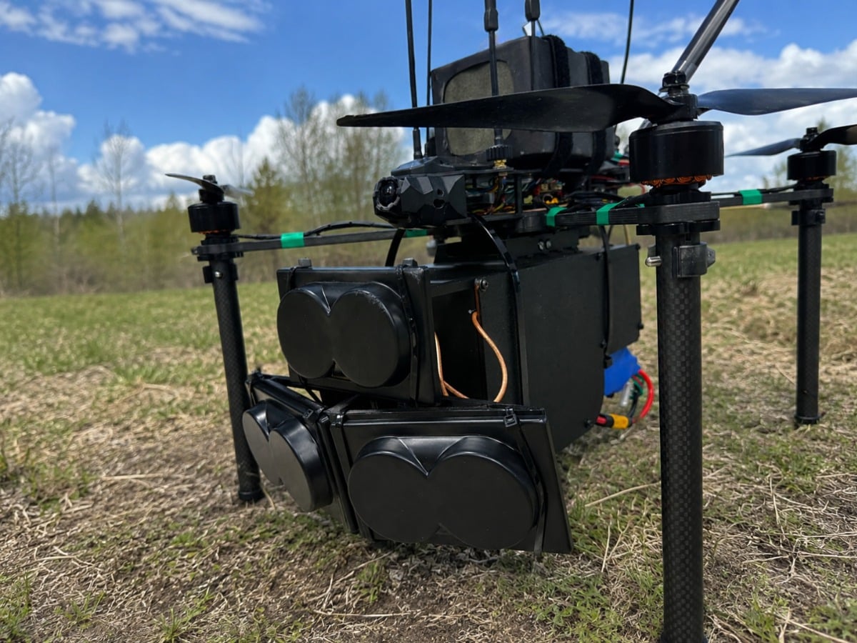
During Exercise Spring Storm, a large-scale NATO training evolution involving 12,000 personnel, the Estonian Defence Forces' Force Transformation Command executed operational field testing of a portable, drone-based signals intelligence system. The exercise utilized a modular payload developed by Sky Spy, integrated into an MRM2-10 small unmanned aerial system platform manufactured by Orqa, operated in conjunction with the 131st Infantry Battalion. This deployment establishes a precedent for tactical-level electromagnetic reconnaissance, moving signals intelligence capabilities from strategic, high-altitude assets down to organic battalion-level operations.
The Physics of Terrestrial Signal Attenuation and the Elevation Advantage
The primary bottleneck for ground-based radio frequency sensing is the radio horizon. For a ground sensor placed at a height of 2 meters, the theoretical line-of-sight horizon across perfectly flat terrain is approximately 5 kilometers. Complex terrain features, such as dense forest canopies or urban infrastructure, introduce severe diffraction and multipath scattering, which exponentially degrade signal strength.
The relationship between distance, frequency, and path loss in free space is governed by the free-space path loss formula:
$$FSPL = \left(\frac{4\pi d}{\lambda}\right)^2$$
Where $d$ is the distance between the transmitter and receiver, and $\lambda$ is the signal wavelength. In terrestrial environments, this loss is exacerbated by ground-reflection attenuation, shifting the power loss relationship from an inverse-square law ($d^2$) closer to an inverse-fourth-power law ($d^4$) near the surface.
Elevating a radio frequency sensor to an altitude of 100 meters via a tactical unmanned aerial system alters these geometry dynamics completely:
- Radio Horizon Expansion: Elevating the sensor to 100 meters expands the theoretical geometric horizon to over 35 kilometers, effectively increasing the geographic area of coverage by a factor of seven compared to a ground-based sensor.
- Mitigation of Obstruction Loss: Raising the receiver above the terrain line eliminates the absorption and shadowing caused by ground obstacles, transforming non-line-of-sight profiles into clear line-of-sight paths.
- Reduction of Multipath Interference: By capturing signals from an elevated angle, the sensor reduces the reception of ground-reflected waves that cause phase cancellation and signal distortion.
This altitude adjustment enables the detection of low-power, highly directional tactical transmitters that would otherwise remain invisible to ground-based monitoring stations.
The Architecture of Micro-Signals Intelligence Payloads
Integrating a signals intelligence system into a tactical unmanned aerial system requires severe optimization across three engineering vectors: mass, power consumption, and processing capacity. Traditional military signals intelligence platforms are heavy, power-dense systems mounted on large aircraft or armored vehicles. Shifting this capability to a portable multirotor platform requires a re-engineering of the RF frontend and processing pipeline.
+-------------------------------------------------------------------+
|                     MRM2-10 UAS Platform                          |
|                                                                   |
|   +-----------------------------------------------------------+   |
|   |                 Modular Sky Spy SIGINT Payload            |   |
|   |                                                           |   |
|   |  [ Ultra-Wideband Antenna Array ]                         |   |
|   |                 |                                         |   |
|   |                 v                                         |   |
|   |  [ Software-Defined Radio Frontend ]                      |   |
|   |                 |                                         |   |
|   |                 v                                         |   |
|   |  [ Onboard Edge Compute Module ]                          |   |
|   |    - Spectrum Scanning & FFT                              |   |
|   |    - Signal Demodulation                                  |   |
|   |    - Local Metadata Generation                            |   |
|   +-----------------------------------------------------------+   |
|                 | (Compressed Telemetry)                          |
+-----------------|-------------------------------------------------+
                  v
       [ Tactical Datalink ]
                  |
                  v
     [ Ground Control Station ] ---> [ Artllery / Striking Units ]
Sensor Hardware Constraints and Solutions
The payload deployed in Exercise Spring Storm uses a modular, drone-agnostic architecture. The hardware stack consists of an ultra-wideband antenna array, a software-defined radio frontend, and an onboard edge computing module.
Weight represents the primary constraint on multirotor flight duration. Every gram of payload directly scales the current draw of the propulsion motors, shortening the operational window. The integrated system maintains a strict mass budget, allowing the multirotor platform to sustain tactical flight profiles while carrying the dedicated scanning equipment.
Power distribution presents a secondary challenge. The software-defined radio and processing units must draw power from the main flight battery or an isolated micro-battery pack without introducing electromagnetic interference into the drone’s internal telemetry and control systems. High-frequency processing chips generate thermal energy that requires passive, lightweight heatsinks optimized for airborne airflow to prevent thermal throttling during high-duty spectrum sweeps.
Onboard Edge Processing Versus Datalink Bottlenecks
Raw radio frequency IQ data contains immense volumes of information. Streaming uncompressed spectrum data from an airborne drone to a ground station requires high-bandwidth datalinks that are highly susceptible to electronic jamming and reveal the drone’s own position through high RF emission levels.
To bypass this operational bottleneck, the system utilizes edge compute modules to execute real-time processing directly on the drone. The onboard system executes fast Fourier transforms to scan designated frequency bands, detects deviations from background noise thresholds, and extracts signal metadata. This metadata includes parameters such as:
- Center frequency and instantaneous bandwidth
- Signal modulation characteristics and pulse repetition intervals
- Time of arrival and relative signal strength indications
By transmitting only distilled metadata packets rather than raw signal streams, the required datalink bandwidth drops by orders of magnitude. This compression permits the system to operate over low-bandwidth, frequency-hopping tactical networks that are far more resilient to enemy electronic countermeasures.
Operational Logic of the Geolocation Process
Locating an enemy emitter from an airborne platform involves converting raw radio frequency measurements into precise geographical coordinates. The system uses two primary methodologies to achieve target geolocation: received signal strength indication mapping and angle of arrival profiling.
Received Signal Strength Indication Mapping
As the drone traverses a pre-programmed flight path, the onboard payload continuous records the power level of the targeted emission. By cross-referencing these power measurements with the exact GPS coordinates and altitude of the drone at the microsecond of interception, the system constructs an RF intensity matrix.
The primary limitation of this technique is its vulnerability to signal fluctuations caused by atmospheric conditions, transmitter power variation, and antenna orientation. The system compensates for these variables by executing mathematical algorithms that calculate probability density functions over a geographic grid, narrowing the possible location of the emitter as more data points are collected during the flight.
Angle of Arrival Profiling
By utilizing a multi-element antenna array on the underside of the aircraft, the payload can determine the direction from which a wavefront hits the sensor. The phase difference of the arriving signal across the different antenna elements provides a vector pointing toward the emitter.
When the drone moves along its trajectory, it takes multiple bearing measurements from different geometric positions. The intersection points of these directional vectors form a triangulation web. The accuracy of this geolocation method scales with the baseline distance between measurements and the angular resolution of the antenna array.
This dual-method approach allows the tactical unit to identify the location of hostile command elements, such as drone pilots or active jammers, before those systems can relocate or suppress the detection platform.
Tactical Integration and Countermeasures
The deployment of an airborne signals intelligence system alters the tactical cycle of battalion-level operations. In modern high-intensity conflicts, detecting the control infrastructure of an uncrewed asset is highly prioritized over neutralizing the asset itself. Locating the control station or jammer permits the execution of counter-battery artillery fires or loitering munition strikes directly against high-value human assets and hardware systems.
System Limitations and Vulnerabilities
Despite its geometric advantages, airborne signals intelligence possesses distinct operational vulnerabilities that prevent it from being a universal solution:
- Aerodynamic and Weather Limitations: Small tactical drones are highly susceptible to adverse meteorological conditions. High winds, heavy precipitation, and icing conditions degrade flight stability, which introduces angular errors into the angle-of-arrival calculations and can ground the assets entirely.
- The Problem of Spoofing and Decoys: Competent adversaries do not emit continuously from static positions. They utilize remote antennas connected via fiber-optic cables to the actual command station, deploy automated decoy transmitters that mimic the electronic signatures of real command posts, and implement strict emission control protocols.
- Kinetic and Electronic Counter-Countermeasures: An elevated drone is highly visible to both optical systems and short-range air defense radars. The moment the drone ascends to bypass the terrestrial horizon, it exposes itself to enemy detection and subsequent hard-kill or soft-kill countermeasure tracking.
Structural Framework of Electronic Reconnaissance Delivery
To successfully implement this capability within a combined arms framework, operations must follow a strict three-phase deployment model.
PHASE 1: SPECTRUM PREPARATION
   |-- Establish local electromagnetic background baseline
   |-- Isolate friendly blue-force emitter frequencies
   +-- Define priority target frequency search windows

PHASE 2: AIRBORNE ACQUISITION
   |-- Execute high-altitude non-linear flight paths
   |-- Conduct multi-angle spectrum sweeps via edge compute
   +-- Cross-reference RSSI and Angle-of-Arrival datasets

PHASE 3: TARGET CONVERSION
   |-- Calculate probability density functions for emitter location
   |-- Convert RF metadata to precise geographic coordinates
   +-- Stream target vectors directly to tactical fire control
The first phase establishes the baseline background environment to avoid wasting processing cycles on friendly emissions. The second phase places the sensor in the optimal geometric plane while minimizing exposure to enemy air defense systems. The third phase translates raw electronic data into actionable kinetic targeting data.
Future refinement of this tactical concept relies heavily on hardening the underlying multirotor platforms against electronic warfare. As adversaries field wider-band, higher-power jamming systems, airborne signals intelligence platforms must increasingly rely on advanced autonomous flight modes that function entirely in GPS-denied environments. This includes integrating optical terrain-relative navigation and inertial guidance packages that allow the platform to maintain stable flight paths and accurate sensor orientation data even when all external satellite navigation and command datalinks are completely suppressed. The units that master the integration of these autonomous airborne sensors into their organic fire support loops will possess a definitive information advantage in the modern electromagnetic arena.